The Circle District Museum is
heated by a hot-water baseboard (and overhead fan-forced) system.
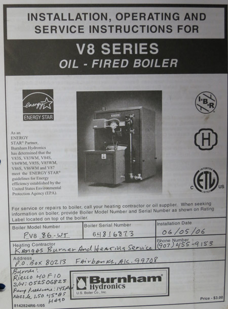
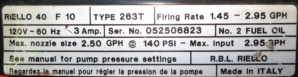
Hot water is supplied by a Burnham V-8 Series Oil-Fired Boiler (
PV86WT - GBWF2S) fitted with
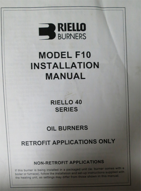
a Riello 40F10 burner. The burner contains a core for domestic hot water.
Boiler and Burner were
installed on June 5, 2006. Much of the system dates back to 1984.
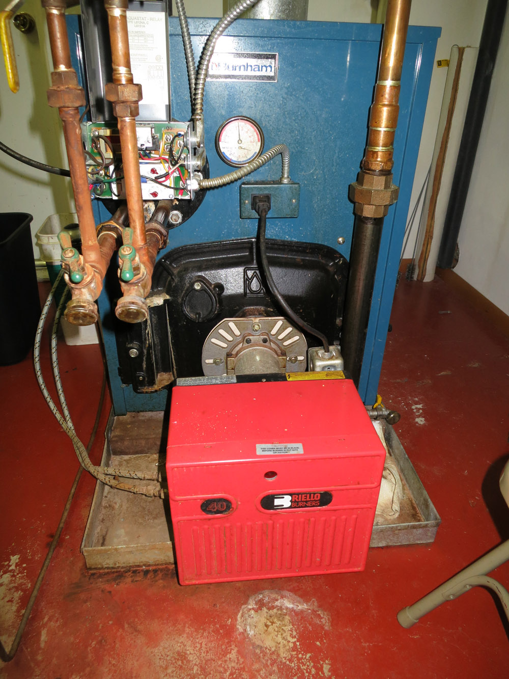
The burner nozzel is a 1.50 45°
ES with an operating pressure of 145 psi. We have four replacement
nozzels as well as three- 150 Steinen 60° H nozzels. The Steinen
nozzels were specified for this burner
however the installer used the 45° nozzels at a higher pressure to
provide a finer droplet size. We
also have a burner repair kit from Riello which has a replacement pump,
motor, etc.
There is a blanket at the top of the
fire chamber which is loose. We have a replacemant blanket
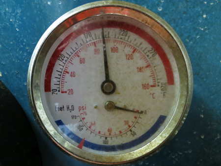
and the adhesive to secure it. The pressure section of our temperature-pressure
gauge (below) behaves
erratically. We do not have a replacement.
The 30 psi pop-off valve needs to be replaced. We have 2 replacment valves.
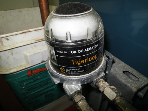
Fuel is
supplied by an undergroud 2000 gallon tank and passes through
a filter (not shown) and then trhough a Tiger Loop. We have replacement
filters
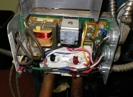
The burner is controled with an Aquastat
relay. Currently this is set to fire the burner at 180° F. with
a
differential of 15° F. and high cutoff of 210° F.
There is an additional Aquastat sensor on the outflow
pipe of the boiler set at 200° F.
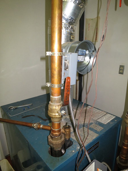
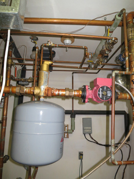
Outflow from the boiler is through a vertical 1-1/4 inch copper pipe with
a shutoff valve just
above the boiler (see above) This turns to the horizontal and passes
through a Spirovent Jr.
with an expansion tank suspended beneath followed by a Grundfos UPS15-42F
T/B2 3-speed
cast iron circulating pump (makeup water system for the boiler is visible
just above the circulating
pump). After the pump, there is a tee. The lower branch (3/4")
feeds the bathroom-hall loop which
returns to a zone valve in the bathroom. The upper branch (1-1/4")
becomes a manifold feeding
the library loop (3/4", toolroom-archives loop (3/4") and the
gallery-office-workroom loop (1-1/4").
The expansion tank and circuating pump were relpaced in February 2015.
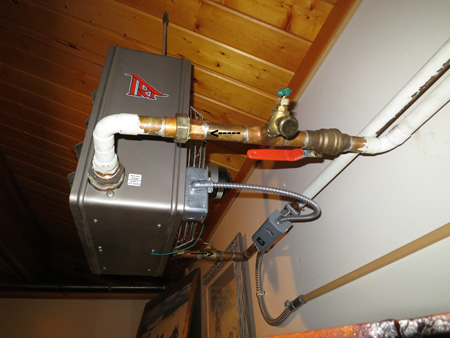
The gallery-office-workroom loop runs
overhead through the bathroom passes through a tee (not
shown). The foot of the tee (3/4") leads through the bathroom
to the west wall of the workroom where
splits by a tee to feed the workroom (3/4") and the office-sale shop
(3/4"). The workroom flow
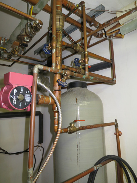
continues to a White-Rodgers 3/4" Zone-A-Flow water valve,
(type 1311-102) on the boiler
intake manifold (below left). The office sale shop flow continues through
the office and sale shop
to its 3/4"zone valve and enters the boiler return line (1-1/4")
from the gallery in the bathroom
(below right).
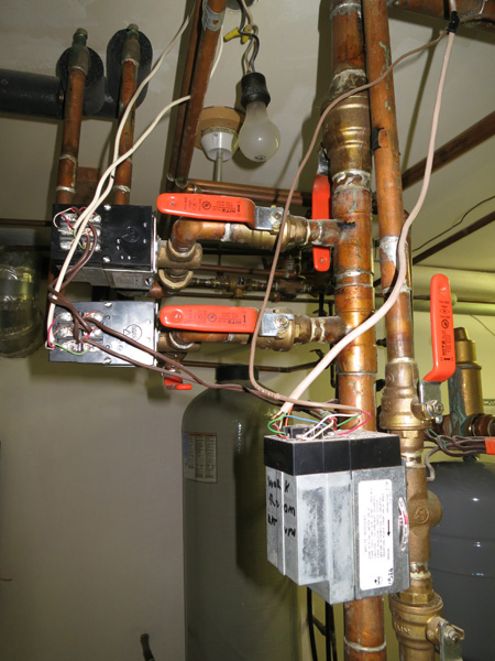
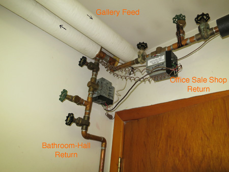
The gallery feed passes from the bathroom
into the hall where it passes through a White-Rodgers 1-1/4"
Zone-A-Flow water valve,type 1311-104 (below left). This zone valve was
placed on the feed line by mistake
in 1985. Perhaps the feed line was originaly meant to be the return line.
This line continues through
the hall and into the gallery branching (below right) to feed the two
overhead fan-driven radiators. The
east fan is on a short run.
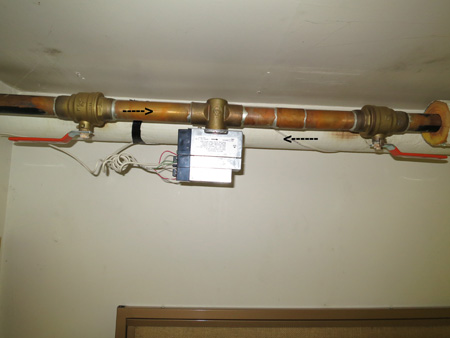
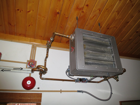
while the west fan is roughly 24'from
the branch
The six zone valves (one 1-1/4"
and five 3/4") are powered by two transformers located to the
left, above and in front of the boiler
![]()
Museum Floor Plan